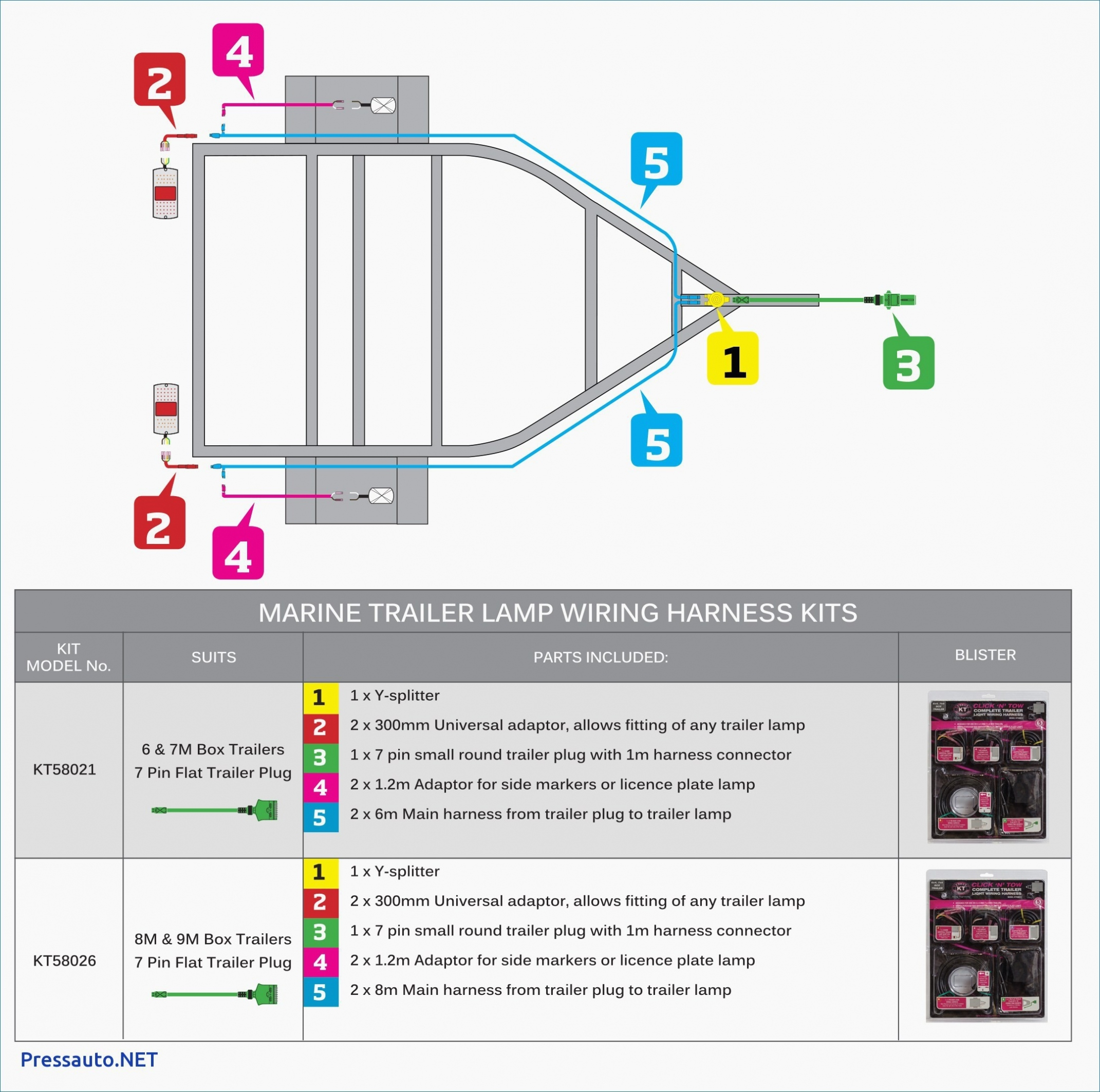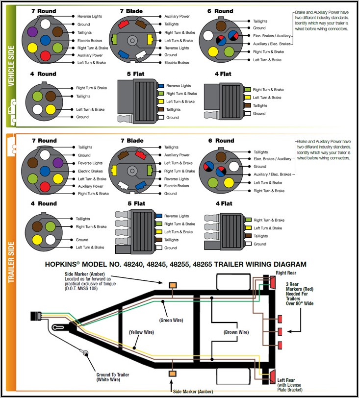
Even with just a few wires, sometimes things go wrong, and you may not have things work, such as your running lights. Check with a test light or VOM.A 4 pin connector is used in many applications, including a utility trailer or boat trailer. Uses: heavy duty landscaping trailer, car trailer, boat trailers, horse trailer, travel trailer, construction trailer, etc. Round 2″ diameter connector allows additional pin for auxiliary 12 volt power or backup lights. Uses: horse trailer, travel trailers, landscaping trailer, car trailer, etc. Round 1 1/4″ diameter metal connector allows 1 or 2 additional wiring and lighting functions such as back up lights, auxiliary 12v power or electric brakes. Note: The black (sometimes red) 12v and blue electric brakes wire may need to be reversed to suit the trailer. The additional wire is tapped into the backup lights to disengage the hydraulic trailer coupler (actuator) when the vehicle is reversing, thus turning off the trailer’s brakes. Typically the 5-Way Flat is used for trailers with surge brakes or hydraulic brakes. Same as 4 way system listed above but adds a extra blue wire for brake signal or auxiliary power.ĥ-Way connectors are available allowing the basic hookup of the three lighting functions (running, turn, and brake) and besides the ground, one pin is available to provide support for another function.
#4 pin trailer wiring diagram license#
Dual Purpose Bulb SystemĬonnect To Blue Wire From Brake ControllerĤ way flat molded connectors allow basic hookup for three lighting functions turn signal / stop light ( green), turn signal / stop light (yellow), taillight / license / side marker (brown) and a ground (white). The male end is mounted on the vehicle side and the female on the trailer side. Choose a connector that has the required number of pins for the functions required. Various styles of connectors are available with four to seven pins to allow transfer of power for the lighting as well as auxiliary functions such as electric trailer brake control, backup lights etc. Connectors are used between the two to allow disengagement when not towing. This is accomplished by tapping into the tow vehicle’s electrical harness to transfer power to the trailer wiring system. Just wire the appropriate wires to the ones described above and then wire the ground to a good ground at the frame.īy law, trailer lighting must be connected into the tow vehicle’s wiring system to provide trailer running lights, turn signals and brake lights. Your new harness will tell you which wire is for what. You will also see a Brown wire which is the taillight wire. This is the wire for the right stop/turn signal light. If you look in the wiring going to the right you will find an Orange wire with a Light Blue stripe. This is the wire for the left stop/turn signal light. If you look in the wiring going to the left you will find a Light Green wire with an Orange stripe. The wire is in plastic tubing and splits off to the left and right taillights. When you look at the rear underside of the bed there is a wiring harness with a plug at the left rear end of the frame.

It includes the ground, taillight, and stop/turn signal connections. Let’s face it, if you own a truck, sooner or later you’ll find yourself needing or wanting to tow something.


Many Ranger owners have step bumpers with towing capabilities or have added a hitch.


 0 kommentar(er)
